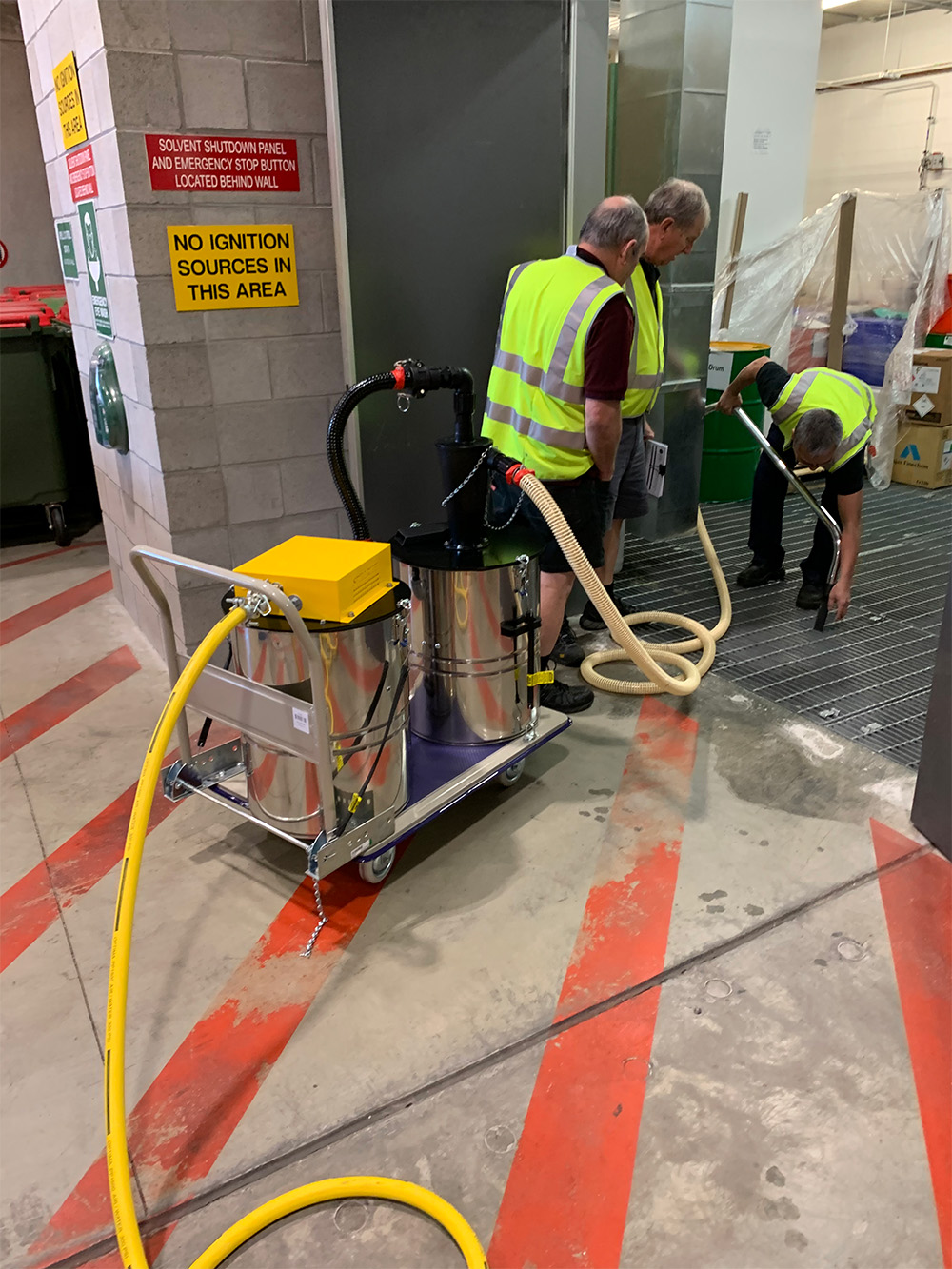
A zone classification is a statement about risk: it says an explosive atmosphere is either present, likely, or possible in that part of the plant. Once an area carries that label, every piece of equipment taken into it — including the vacuum used to clean it — has to be selected against the same classification.
That is the practical problem this range solves. A general-purpose industrial vacuum has an electric motor, brushes, a switch and a plastic body that accumulates charge. Each of those is a potential ignition source, and none of them can be argued away on a site where fuel vapour or a dust cloud may be present. The alternative is a vacuum with no electrical system in it at all.
The four zones, and what they mean on the floor
Zones are split into two families — gas and vapour, and combustible dust — and then graded by how often the explosive atmosphere is expected to be there.
- Zone 1 (gas / vapour) — an explosive atmosphere is likely to occur in normal operation. Tank farms, fuel transfer points, solvent handling, drilling floors.
- Zone 2 (gas / vapour) — unlikely in normal operation, and short-lived if it happens. The buffer areas around Zone 1 equipment.
- Zone 21 (dust) — a combustible dust cloud is likely to occur in normal operation. Inside and around silos, mills, conveyor transfer points, bagging lines.
- Zone 22 (dust) — a dust cloud is unlikely, but settled dust layers exist and can be disturbed. Most of the floor area in a plant that handles powder.
Zone 22 is the one that gets overlooked, because nothing looks dangerous when you walk through it. Settled dust on beams, ledges and cable trays is only inert while it stays put; a poorly chosen vacuum is exactly the thing that lifts it into suspension.
Why compressed air answers the classification
Every Spillrite hazardous-zone unit generates suction with venturis. Compressed air is forced through a shaped throat, air velocity rises, pressure at the throat falls, and that pressure difference becomes the vacuum. Nothing rotates. Nothing rubs. Nothing switches on and off.
The consequences matter more than the physics. There is no armature to arc, no thermal overload to trip, no bearing to run hot and no carbon brush to spark as it wears. The machine has no duty cycle in the conventional sense either — it will run continuously for as long as the compressor keeps up, which is how these units end up in shutdown work where an electric vacuum would be thermally cycling all day.
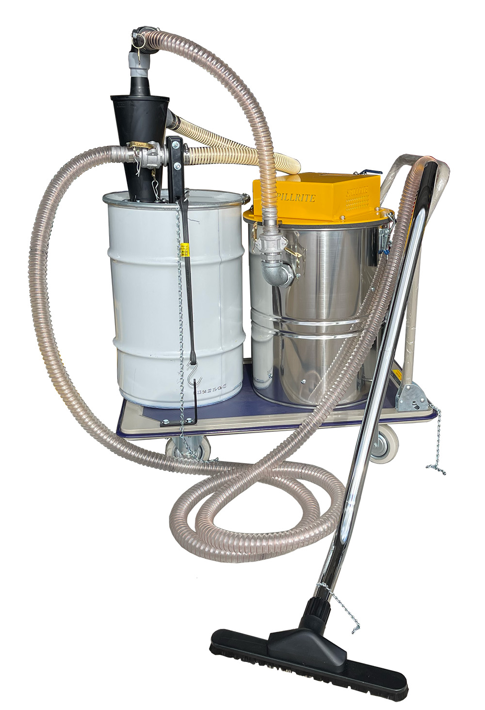
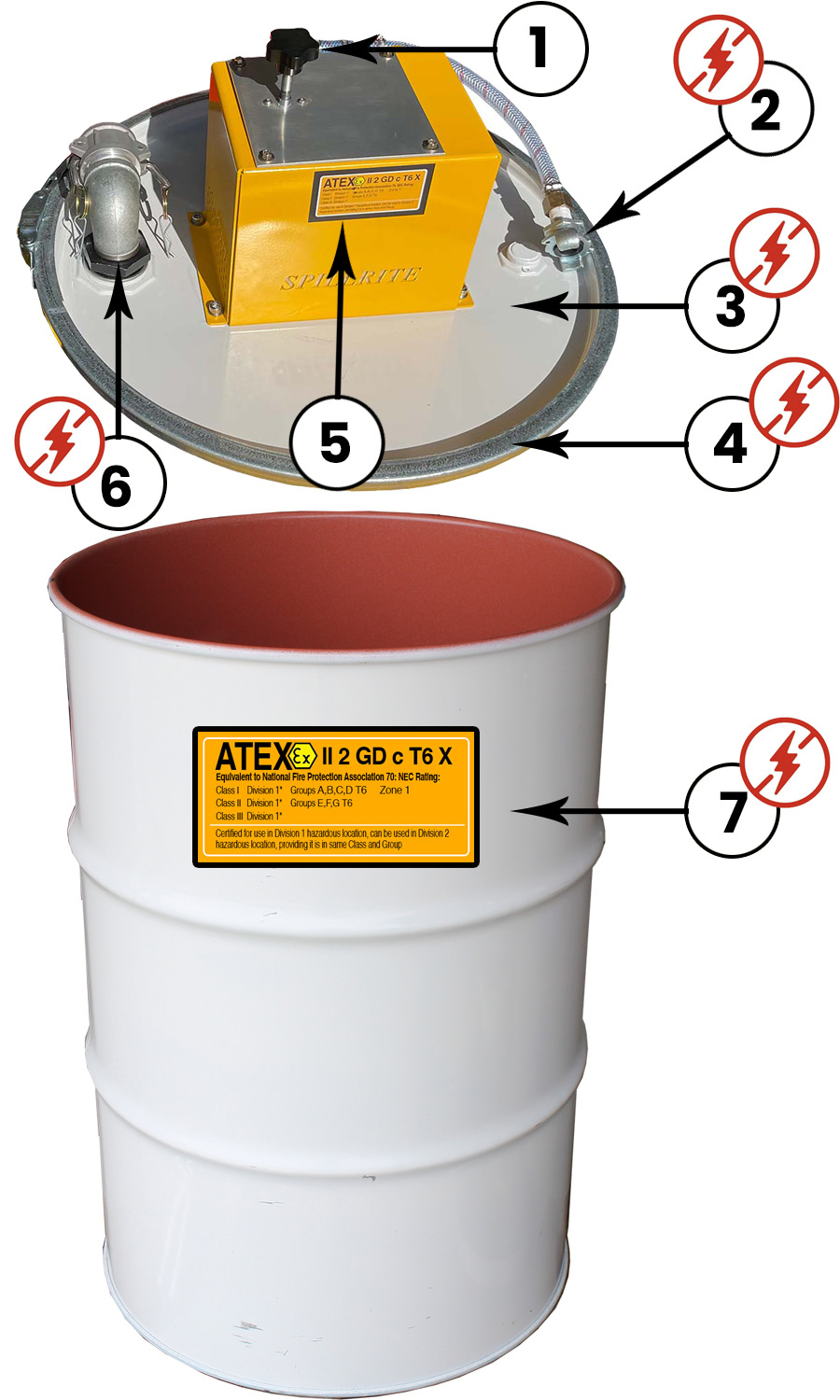
The second half of the answer is static control. Air flow over a hose wall generates charge whether the machine is electric or not, so the whole assembly is built as a continuous conductive path: metal intake fittings, an anti-static hose with its helix wire terminated onto the wand or camlock, metal wands and tools, a bonded lid or base plate, and a grounding chain or strap from the frame to earth. On drum-mounted units the lock ring does part of that work — securing the band ties the lid electrically to the drum, so the two become one earthed body rather than two charged ones.
Matching air supply to hose run
The most common specification error is not the machine — it is the hose. Vacuum is lost along the run, so a unit sized for a bench job will disappoint on a tank deck thirty metres from the drum. As a starting point for 38 mm hose:
| 60 CFM air supply | 5–10 m of 38 mm suction hose |
|---|---|
| 90 CFM air supply | 10–15 m of 38 mm suction hose |
| 120 CFM air supply | 20–25 m of 38 mm suction hose |
| 180 CFM air supply | 25–35 m of 38 mm suction hose |
| Air line to the machine | 1/2" minimum, 3/4" preferred |
| Coupling | Universal claw — do not substitute a push-in fitting |
Undersized air line is the second most common cause of disappointing performance, and it is invisible — the machine sounds normal and simply does not lift. Run 3/4" to the unit wherever the distance from the receiver is more than a few metres, and keep the claw coupling that was supplied with it.
Where these units earn their keep
- Grain handling and milling — silo bases, elevator pits and the settled layers above head height.
- Food manufacturing — flour, starch, sugar and milk powder, all of which form explosive clouds at the right concentration.
- Fuel storage and distribution — bunded areas, transfer points and pump pits where vapour is the hazard rather than dust.
- Offshore platforms and drilling — classified throughout, with compressed air already reticulated to the work fronts.
- Powder coating and paint — booth cleaning and reclaim, where fine organic powder is the product.
- Metal finishing — aluminium, magnesium and zinc dusts, which are both explosive and a health exposure.
- Defence and munitions — propellant residues and casing debris.
- Toner and cartridge recycling — a fine, highly chargeable plastic dust.

Specifying one for your site
Four answers are enough for us to put a configuration in front of you: the zone the equipment will work in, what you are recovering (dry dust, fluid, or both), the furthest point from where the machine will stand, and the compressed air you can actually deliver at that point — not the compressor plate rating, but what arrives at the hose.
From there it is a question of format. A drum-mounted head is the cheapest way to get certified capacity if you already run steel drums. A trolley unit with a cyclone suits continuous dust work where filter loading would otherwise stop the job. Fluid recovery with reverse pump-out suits anyone who has to get the waste into a second container without lifting it. Those formats are covered in the related categories below.